Modifying the Yaesu DR1 Repeater
for use on Allstar
SEE THE UPDATE ON THIS ARTICLE BELOW!
Introduction
The Yaesu Fusion DR1 repeater was released in the spring of 2014 and was offered to amateur radio clubs and organizations for free. Since then an updated DR1X repeater has been released and Yaesu offered DR1 owners an upgrade to it for a nominal fee. The DR1 was considered a beta product and many mostly minor deficiencies were corrected in the newer product. I have no idea how many of these are out there but Yaesu was practically giving them away like candy so it is likely that you might already have one or have an opportunity to acquire one in the future.
Without getting into a long diatribe on VHF/UHF digital modes let me just say that in my opinion none of them are acceptable. Dstar is old technology and has about the worst audio, Fusion has a lot of features and somewhat better audio, and DMR has about the same audio with the ability to put two channels in the space that the other repeaters put one. But the bottom line is the audio sucks worse then using GSM on Allstar and who would do that! I am somewhat of an audio aficionado and digital audio even the audio on some of the SiriusXM channels drives me nuts. It is kind of a dumbing down of what we strive for, good clean quality audio. Also Weak signals don't have a clean cutoff but rather a conglomerate of loud and obnoxious noises coming from the speaker that no one can understand that drives me and my dog crazy. Makes you yearn for some good old "picket fencing"! I am certainly biased but I would say good analog FM repeaters linked or controlled by Allstar make a perfect match and will continue to do so into the future. Why we need all these rooms and groups contrived by some manufacturer is beyond me. The same thing can be achieved very nicely with Allstar and the way YOU want it.
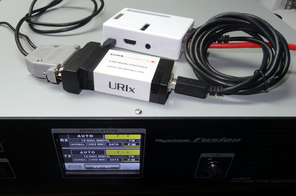
So why would you want to interface a digital repeater with lousy audio to Allstar that has in most cases exceptional audio. The answer is you would not or you should not. So then why this article? Well it turns out in the case of the DR1 (and DR1X) you cannot mix analog audio when the repeater is in a digital mode. The DR1 or DR1X must be fixed in FM (analog) mode both in and out. So that's a good thing, no RF digital audio on Allstar! The DR1 makes a rather good (especially for free) analog repeater. It covers either the 2 or 3/4 meter bands with built-in PL or DCS tone signalling. The repeater as you can see in the photo below is made up of two Yaesu FTM400DR transceivers, a switching power supply, and all the glue electronics to make it a repeater.

Modification
In the DR1, audio and COS/PTT are communicated between the FTM400 receiver and the FTM400 transmitter on a single cable. On the receiver end there is a mini USB connector and on the transmitter end it is a 10 pin mini DIN. If it can be avoided no one wants to fool around with wiring these tiny connectors! So the answer is to cut the cable and make a breakout board. The cable has 8 wires and is shielded. 6 of the wires are just soldered together on the breakout board and not used for connections elsewhere. One wire (RED) is the audio from the receiver to the transmitter and another (YELLOW) is receiver COS to transmitter PTT. These are the two wires we will use in the modifications. In addition the Orange wire is GROUND.
Carefully cut the wire at a location about midway where you will mount the board. Remove the outer jacket at each end for about two inches and twist the braid off exposing the wires. Twist the braid to form a tight wire and strip each wire carefully about 1/8th inch at the ends. Solder tin all the wires and figure out a board where you can connect the wires using solder pads. I used a cut-off protoboard.
Solder the wires including the shields together on the board except solder the red and yellow wires to individual pins not together. Be careful that you match the colors. There are grey and white wires that look very much alike!!
I will describe wiring to a DMK-URI USB interface. If you are using a different FOB wire appropriately. Note though that I am using the 6db gain stage in the DMK-URI. The yellow wires represent COS coming from the receiver and PTT to the transmitter. So the yellow wire from the receiver (mini USB end) would be wired to pin 8 (COS) of the URI and be defined COS. This can be wired directly. The yellow wire to the transmit side (Mini DIN end) is wired directly to pin 1 (PTT) of the URI. The audio is carried on the red wires. The red wire from the receiver (mini USB end) is wired directly to pin 21 (AC audio in) of the URI and the red wire to the transmitter (mini DIN end) is wired directly to pin 12 of the URI (+6db amp out). Pins 22 and 24 on the URI are connected together and also pins 14 and 25. This connects +5V to the internal amplifier. The orange wires are connected but are also ground which is connected to pin 20 of the URI. See the DMK-URI website for more information on connections and schematic diagrams. The audio carried on the red wire is pre-emphasized audio. PL tones are carried on another line to the transmitter and are not needed by Allstar.
Here is a table of the connections -
| Color | From | Function | URI DB25 Pin |
|---|---|---|---|
| Yellow | Receiver | COS | 8 |
| Yellow | Transmitter | PTT | 1 |
| Red | Receiver | RX Audio | 21 |
| Red | Transmitter | TX Audio | 12 |
| Orange | TX/RX | Ground | 20 |
| Connect pins 22 and 24 and pins 14 and 25 on the DMK-URI | |||
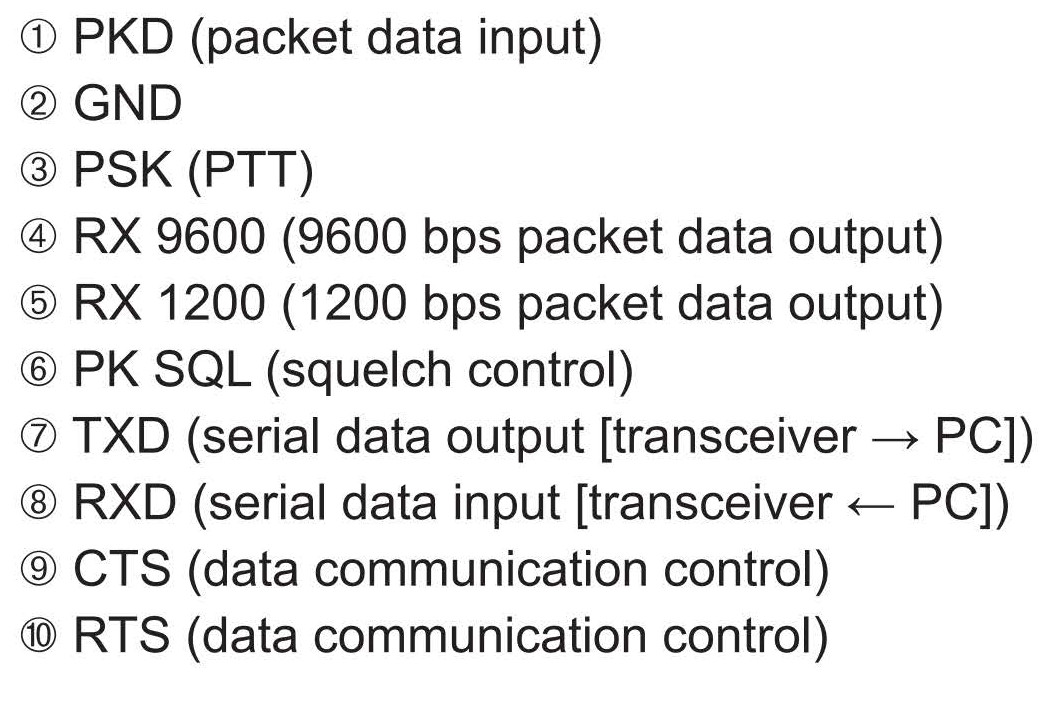
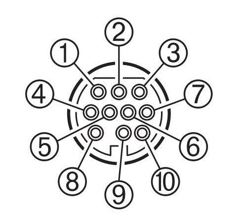
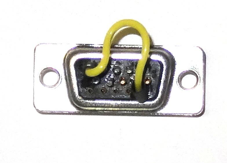
Just for reference here is the mini DIN connections to the FTM400 transceiver
Not all would be used in the DR1
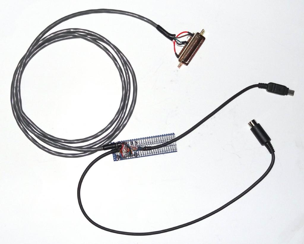
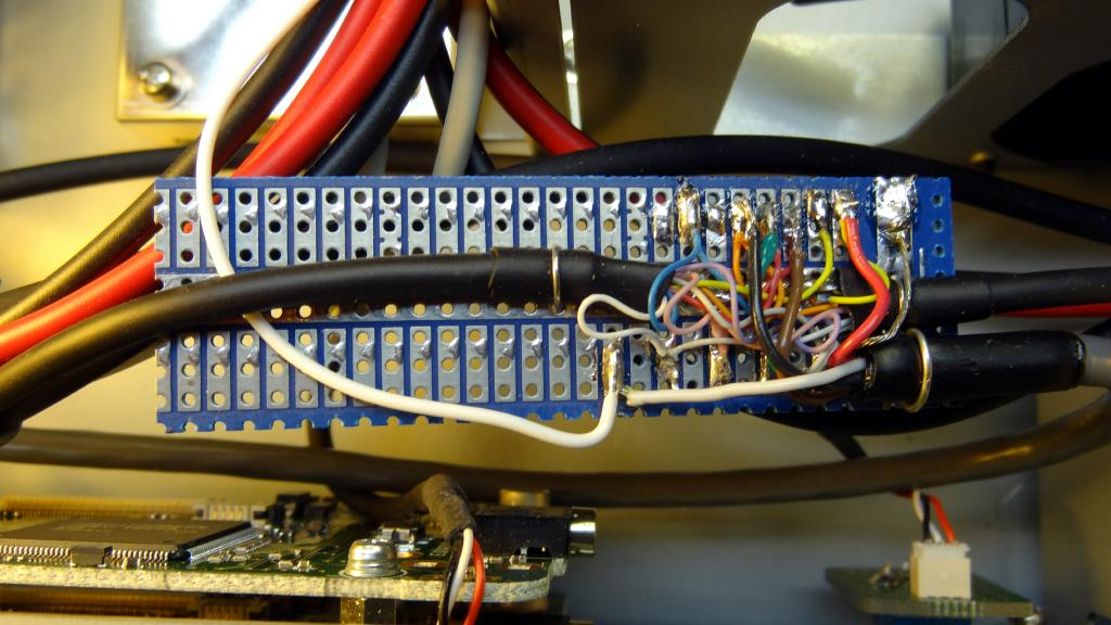
View of the completed wiring harness showing mini USB to Receiver,
mini DIN to transmitter, and DB25 to URI
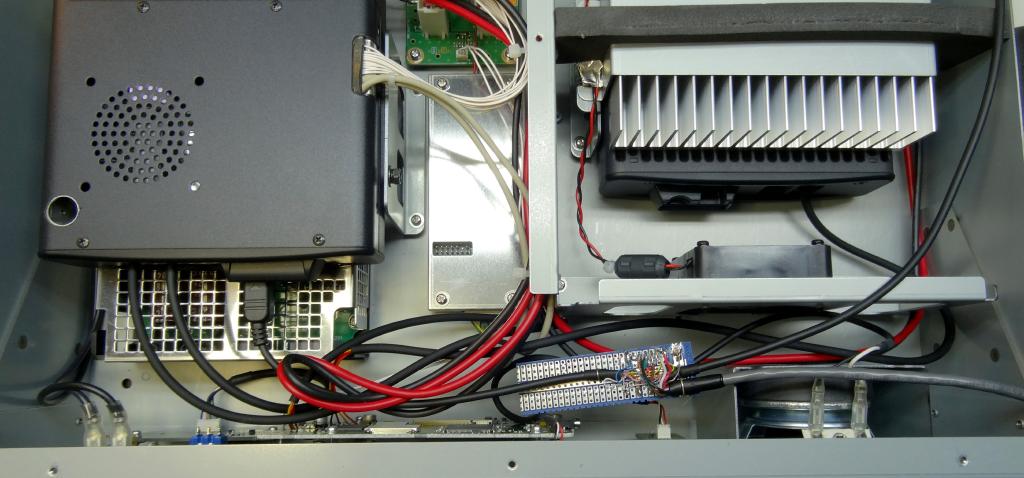
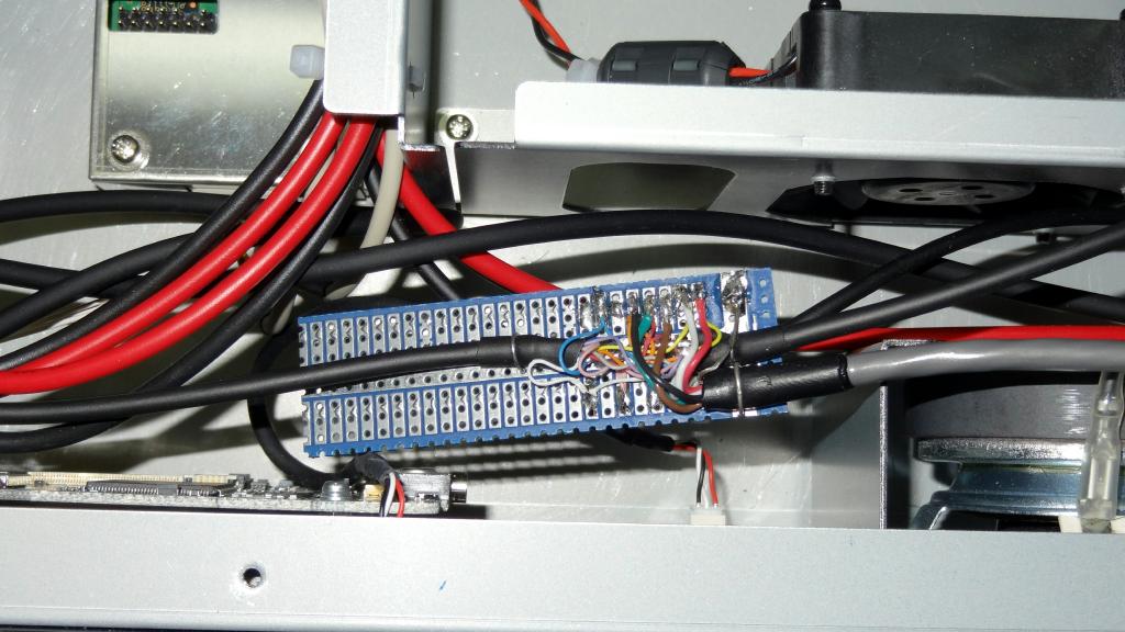
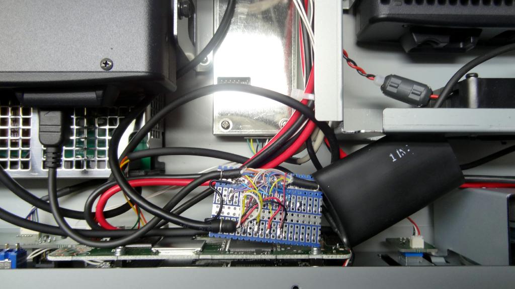
View of the board installed in the DR1 with cables not yet cleanly routed and tied.
UPDATE
After doing the above modification and using the repeater for awhile I decided I did not like the way the repeater was sending the COS signal to Allstar. In the above mod the signal is taken from the yellow wire on receiver (mini USB) end of the cable. The signal on this lead while following the PL input to the receiver has a delay on key-up which is not desirable. When Allstar or any external controller is the controlling DR1 you want it to add any additional tail to the transmitted signal NOT the DR1.
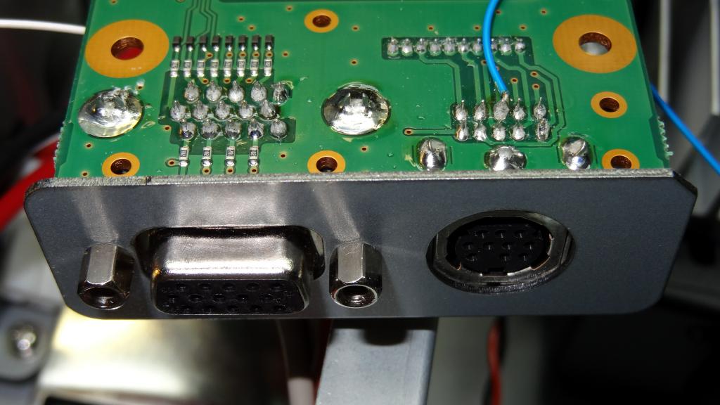
Doing some additional investigating I found two places where COS could possibly be detected. The DB15 control connector on the rear panel pin 4 goes low on signal. Unfortunately it follows squelch not PL so it triggers even with PL into the repeater turned off. Another option is the mini DIN connector next to the DB25 connector. The Squelch pin there does follow PL and does not trigger on non PL input. I wanted to do all wiring internal to the repeater so I soldered to the connector pins on the bottom side of the board. See the photos showing this below.To remove the board remove all connections. The connector with all the loose white wires and the DC connection to the module in front of it can be left on. Remove all the screws and slide the board back and turn it over to access the connector pins.

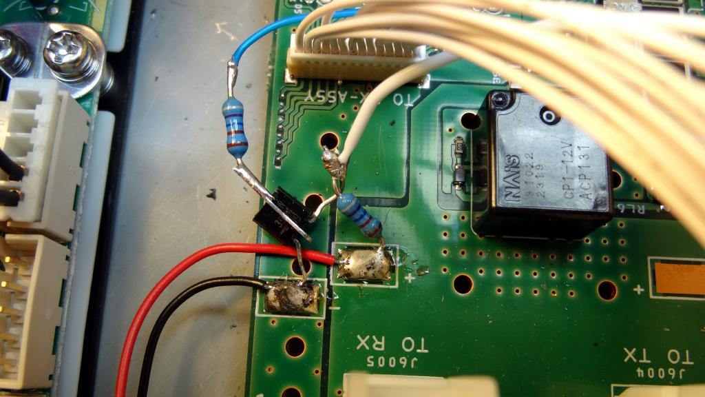
Solder one end of a wire about a foot long as shown to the center pin of the 10 pin connector. The row away from the rear connectors. The photo shows this best. Route the wire up through one of the nearby holes in the board. Remount the board but leave the connections off for now. Unfortunately this connection is the opposite COS polarity that is desirable for Allstar, positive going on signal. When possible it is always better to have a negative going COS level on signal feeding the DMK URI. A 2N3904 was added near the front of the board where the red and black leads that come from the module in front of the board are connected. The emitter is soldered directly to the ground (black wire) pad. The collector is connected through a 10K resistor to the +12V (red wire). The wire from the back connector is wired to the transistors base through a 10K resistor. Then another wire is connected to the Collector and run to the breakout board. The COS line to the external DB25 connector (white wire in the photo) is removed from the yellow lead to the RX mini USB connector and connected on a separate pad to the lead from the collector of the 2N3904 (also a white wire in the photo). Thus the positive going COS from the rear connector is inverted and sent to the DB25 pin 8 for connection to the DMK URI. Again the photos below are the best way to understand this.
Final notes
Here are some additional notes on using the DR1 with Allstar.
- The audio on the red lead is pre-emphasized. You need to de-emphasize the input and pre-emphasize the output in the Allstar SW.
- Simpleusb configuration - rxboost=0, carrierfrom=usbinvert, plfilter=off, pre and de-emphasis on (Latest code will allow both in simpleusb, BBB V1.3, RPI2 V1.0)
- Simpleusb levels with above settings are approximately - RX=650, TX=950 (with URI amplifier)
- NEVER operate the DR1 in high power for any length of time. It is only rated at a 50% duty cycle. The repeater transmitter is just a mobile rig with a heatsink and fan added. Repeaters can be up for hours on end with busy use. Run the repeater at lower power and use an external 100% rated amplifier.
- Turn the ID in the DR1 off. Allstar does all control and ID. Duplex=2 in rpt.conf.
- Set the PL or DCS values and the TX/RX state (on/off) on the DR1. Note if using remote operation see the comment below. PL filtering is not needed in Allstar as the audio is filtered in the DR1 and PL follows a different channel to the transmitter.
- DR1 TX timeout can be set in addition to time-out in Allstar as a safety precaution. Set the DR1 time-out longer than Allstar's timeout.
Both the DR1 and DR1X have a rear panel control connector and it would appear that one could wire these connections there. Don't waste your time trying this on the DR1, it is not implemented. I understand it has been implemented on the DR1X but since I do not have one to play with it is not totally clear how Allstar would be interfaced. When I get one to play with I will update this article. The bottom line is that you want Allstar to be the repeater controller and therefore COS/PTT and RX/TX audio must go in series through Allstar as detailed in this article. It might also be a good idea to wire a dummy female DB25 plug which can be inserted into the DB25 coming from the DR1 to bypass the use of Allstar and put the repeater back into its original configuration. The plug would have pins 1 and 8 (connecting COS to PTT) and pins 21 and 12 (connecting RX to TX audio) jumpered.
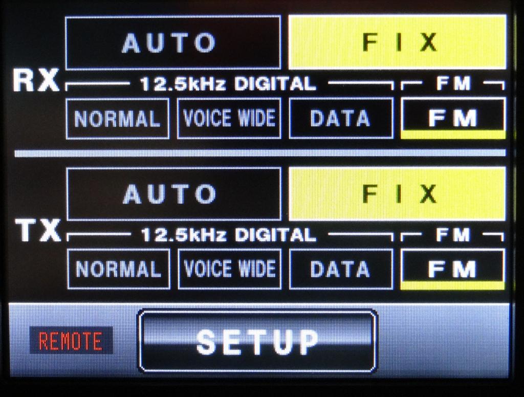
The DR1 (and DR1X) have front panel touch screen setup. This allows a user (or also an unauthorized person) to change modes. For this reason and to also ensure that the repeater comes up in the FM input/output fixed mode at all times it is suggested that you wire a DB15 (3 row) connector and insert it into the rear panel control connector. You would also put the repeater in remote mode at the front panel menu. Once you do this changing modes at the front panel is not allowed and it will be set to the fixed FM input/output mode. The plug (as shown below) has one jumper connection from pin 5 to pin 11. Note that the control connector also has two pins (13 and 14) to control RX/TX tones. Leaving these pins in the open (high) state turns tone encode/decode on. This would be the normal state. The tones could be disabled remotely if desired by switching either or both of these pins low.
Optional DB15 connector wiring for fixed TX/RX FM mode
Additional Photos DR1x mod
Heatshrink over breakout board
Breakout board with wire to TX/RX and external USB FOB
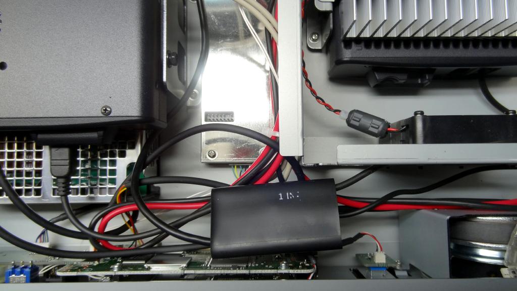
Complete package for Allstar on the DR1x using the RPi2
Conclusion
The Yaesu DR1 serves as a good analog FM repeater interfaced to Allstar. Using a Beaglebone Black or Raspberry Pi 2 with Allstar with or without an Internet connection it makes an ideal repeater package. Allstar is open source and with its built-in Echolink and digital and analog multiple source linking capability it is one of the best packages out there to control your repeater. As a side note when I was removing the DR1 receiver cover I noticed it has a voice module installed. I do not believe this is used in the repeater so if your DR1 has one installed you could probably remove it and use it in a FTM400DR mobile rig. Allstar would supply any voice commands you require in your repeater.
© 2015 - WA3DSP